-
Machine tools
-
Machine tool accessories
-
Welding, cutting equipment
-
OEM Machined parts, components
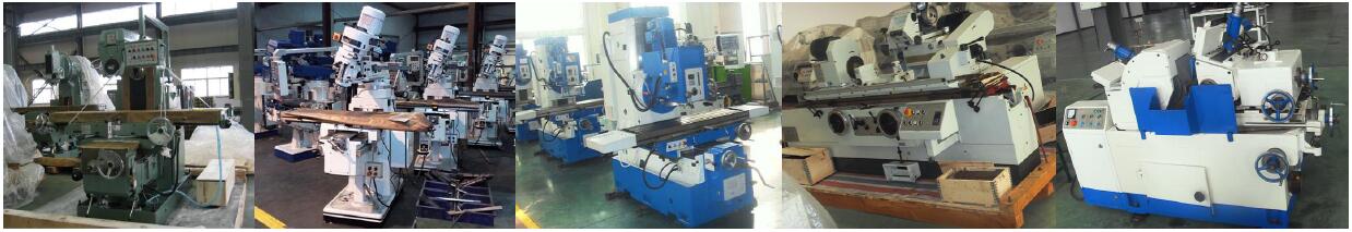
 Horizontal lathes
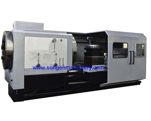
1. General Description
This CNC-OCL520 X 1700 Model CNC Control oil country lathe is widely used to turn the end of various kinds of pipes. Moreover, it has the functions of a general-purposed lathe and can turn the outer cylindrical surfaces, the inner cylindrical surfaces, the end faces, the Metric threads, the Inch threads, the Modular threads and the Diametrical threads, etc.. Carbide tipped turning cutters can be fitted on this lathe to process various kinds of ferrous metals and non-ferrous metals.
This lathe has the rapid traverse mechanism, the end protection and the independent lubrication pump etc.. There are a front chuck and a rear chuck fitted on both ends of the spindle to clamp the long pipes.
This lathe has the advantages of high power, high speed, high rigidity retaining ability and low noisy level. It has pleasing appearance, reasonable layout, convenient operations etc.
The FANUC 0i mate CNC control system and the full-digital AC servo system are equipped on this lathe. Infinitely variable speeds for the main turning motions, two linkage control axes, X-axis and Z-axis are controlled with semi closed loop and the high-quality precision ball screws pairs enable the lathe the high positioning accuracy and the high repeatability accuracy.
2. Specifications
|
Model |
CNC-OCL520 X 1700 |
|
|
|
|
General Parameters |
|
|
Swing over bed |
1200 mm |
|
Swing over cross slide |
610 mm |
|
Bed width |
755 mm |
|
Maxi. workpiece length between centers |
1700 mm |
|
Spindle bore diameter |
520 mm |
|
Pipe threads diameters range |
330 - 510 mm |
|
Headstock |
|
|
Spindle speeds |
6- 205 RPM, 9 Steps |
|
Spindle bore diameter |
520 mm |
|
Main motor power |
37 KW |
|
Feeding System |
|
|
Tool post cross travel |
500 mm |
|
Carriage longitudinal travel |
1250 mm |
|
Tool Post |
|
|
Vertical distance from spindle centerline to tool mounting datum plane |
40 mm |
|
Tool shank sectional size |
80x80 mm |
|
|
|
|
Tailstock |
|
|
Diameter of quill |
140 mm |
|
Quill travel |
300mm |
|
Taper of quill bore |
MT #6 |
|
Tailstock cross adjustment |
±25 mm |
|
Power Supply |
|
|
Main motor |
37 KW, 1460 RPM |
|
Clamping motor |
3 KW, 1420 RPM |
|
Gear pump |
2.5 MPa, 1450 RPM |
|
Cooling System |
|
|
Coolant pump |
0.15 KW, 22 L/Minute |
|
Overall Size and Net Weight |
|
|
Overall size, LxWxH |
5000x2200x1750 mm |
|
Net Weight |
15000 KG |
3. Main Components
3.1 Machine Base
The one-piece construction machine base, the headstock frame, the carriage case, the cross slide and the tool post are made of the high-strength and high-density close grained HT-250 grey cast iron with the resin sand casting processes. They have been processed with three steps of aging treatments including the natural aging treatment of more than 6 months to eliminate the internal stress and retain their stable accuracy in a long time. With the features of the high rigidity and the high distortion-resistance, they support heavy cutting and sustain high machining precision for a long time.
II-shaped reinforcement ribs on the bed base offer high rigidity, high vibration-resistance and high sectional distortion resistance. The bed base is slant by 45 degrees and the chips can be removed conveniently out the back of the lathe. The bed base has been analyzed with the advanced FEA technology to theoretically verify the bed base structure’s reasonability in design, premium rigidity, vibration-resistance and sectional distortion-resistance.
Bed ways have been supersonic frequency induction quenched and precision ground on a precision guide way grinder. PTFE anti-abrasion soft belts with low friction coefficient are coated on the guide ways on both the carriage and the cross slide to improve the precision of the bed ways and prolong the service life of the lathe.
3.2 Headstock
The 37 KW powerful AC variable frequency motor is controlled by the AC frequency conversion control system and drives the spindle through the narrow V belts and the speed-changing mechanism. The spindle, being shifted in nine steps, runs at infinitely variable speeds in a range of 6 – 205 RPM.
The main transmission system has the optimum design and features high power, high precision, wide speed range, high efficiency, simple structure and convenient operations. Therefore, the turning tools’ processing characteristics can be maximized and the workpieces in various sizes are under the best cutting conditions. Thus, the lathe’s capacity is maximized to enable the machine to perform high efficiency in production. Meanwhile, this lathe has the advantages of high precision transmission, optimum torque characteristics, high spindle speed, stable transmission and compact structure.
The spindle has been properly heat treated and fine machined to have even metallurgical structure, high rigidity and high toughness. It can carry high torque and will not distort under heavy cutting. The spindle adopts two-point supporting design. The reliable bearing configurations and spacing design, combined with the high-precision spindle bearings, offer the lathe high revolution accuracy, high spindle rigidity, weight-loading capacity and low temperature rising and thermal deformation. The optimum designs in the transmission system and the gears processed with high frequency quenching and precision grinding offer the headstock low noise, high transmission accuracy and high output torque.
One 4-jaw independent chuck is fitted in the front of the spindle, the other 4-jaw chuck is fitted in the rear of the spindle. The clamping and unclamping of both chucks are operated by hand.
3.3 Feeding Movements
Both the Cross feeding (X axis) and the longitudinal feeding (Z axis) are driven by an independent AC servo motor via the synchronous toothed belt and the precision ball screw pair. Thus the rapid traverses and feeding movements on both the X axis and the Z axis are performed at infinitely variable speeds. The X axis and the Z axis are controlled with semi closed loop using the encoder.
Both the ball screw on the cross direction (X axis) and the ball screw on the longitudinal direction (Z axis) are supported by two sets of special bearings mounted in the “face-to-face” matching pattern to form the “fixed-fixed” supporting style. The ball screws have been pre-loaded and pre-stretched to have high accuracy and high axial rigidity.
The carriage guide ways are processed with medium frequency quenching and precision grinding and coated with PTFE to prevent the carriage from taking the stick-slip motions on the guide ways. Thus the positioning accuracy and the repeatability accuracy on this lathe are perfectly ensured.
3.4 NC Turret
4-Station NC turret is equipped with this machine. It features high precision with repeatability of 0.005 mm, stable swivel and simple motions.
3.5 Tailstock
The design of the stock features high rigidity, loading capacity and convenient operations. The center in mounted internally. The diameter of the quill is 140 mm and it has high rigidity and revolution accuracy.
The tailstock consists of the upper body and the lower body. The spindle and the spindle centerline adjusting mechanism are mounted in the upper body. The tailstock moving mechanism is mounted in the lower body. The tailstock is mounted on the bed ways and is driven to move longitudinally through the engagement of its gear on the bottom of the lower body and the rack on the bed way side.
At the beginning of operating the tailstock to support the workpiece, drive the whole tailstock to approach the workpiece rapidly by running the gear at the bottom of the lower body on the tailstock. When the whole tailstock is close to the workpiece, stop it and drive the quill on the upper body of the tailstock slowly to push the workpiece until the center firmly supports the workpiece, then stop the quill travel in the upper body of the tailstock.
3.6 Cooling System
Under the foundation level of the lathe, there is a special coolant reservoir. The coolant is pumped out and flows along the pipeline to the cutting area to improve the cutting conditions. The coolant, flowing away from the cutting area, is recycled into the coolant reservoir via the chip removing channel underneath the machine base. Thus the coolant will not pollute the environment.
3.7 Lubrication System
The central quantitative automatic lubrication device lubricates the ball screw pairs and bed ways periodically.
3.8 Hydraulic System
The hydraulic system lubricates the headstock and the automatic shifts of the changing gears in the headstock. The main hydraulic components are made in Taiwan. The hydraulic system works reliably and is convenient to maintenance.
3.9 Electricity System
The electricity controls the force electricity and the weak electricity and effectively combines the functions of the mechanism system and the electricity system on this lathe. Therefore, this lathe can be conveniently controlled and operated.
3.10 Auxiliary Supporting
The auxiliary supporting device is available as an option for this lathe. In case the workpiece is long and has to pass through the spindle bore and overhangs with a big length at the rear of the headstock, the auxiliary supporting device can be used to support the workpiece in order to get more stability and reliability in turning processes.
4. CNC Control System and Electricity Cabinet
4.1 CNC Control System
FANUC 0i mate Model CNC control system, made in Japan. Its main functions are as below:
4.1.1 Fixed Cycle of Turning
In this fixed cycle of turning, there is a program segment of G function to take the cutting processes accomplished by multi program segment commands. All the operator need to do is to input the command data, and then the tool path of the cutting process is automatically generated to simplify the programming.
4.1.2 Storage Type Pitch Error Compensation
For position errors such as the pitch error on the feeding ball screw on either X-axis or Z-axis, use the reference point as the compensation origin and store the data to be compensated for into the CNC Memory at the compensation intervals set on each axis. Then use the minimum movement graduations to compensate for the mechanism position errors.
Compensable Axes: X-axis, Y-axis, Z-axis and the 4th axis
Compensation Points: 128 Points on each axis
Compensation Size: 0 - ±7x magnification
Compensation Magnifications: x1, x2, x4,x8
Compensation Interval: 8000 – 9999999
Graduation: 0.001mm
4.1.3 Mechanical Zero and Graphic Function
Using the zero stopper on each axis on the lathe, the operator can use automatic mode or manual mode to return to the mechanical zero point, thus the mechanical position errors are eliminated and the pass ratio of the finished products and the productivity are increased.
The graphic function realizes the preview of processing program and the indication of the actual tool path. The drawing coordinate system, the drawing center point and the scales, etc. can be set with the graphic parameters, thus the conditions of workpiece on all positions can be observed.
4.1.4 U Disk Interface
The data such as the system parameters, the programs can be transmitted. The system software can be upgraded using the U disk. And the U disk can help to take high-speed DCN processing (K1000M).
4.1.5 Rigid Tapping Function
The system is configured with the servo spindle. The servomotor drives the spindle to perform high-speed and high-efficiency tapping. The interpolations between the tapping spindle and the headstock spindle perform the rigid tapping. The tapping spindle feeds for a distance equal to the thread pitch responding to each turn of the spindle in headstock.
4.1.6 Open PLC Functions and CAN Bus Interface Functions
The special software for PC machine is used to compile the PLC ladder chart. The PC machine is connected to the system and tested. On the system the ladder chart is shown. There are 14 basic commands and 58 functional commands. The command scanning cycle is 16 – 32 ms, 0.5 μs/step and maximum 16000 steps.
The CAN bus’s extension digital I/O interfaces and analog I/O interfaces are available with data scanning cycle of 16 ms and communication distance of 100 m, and are used on machine panels, NC panels, remote I/O modules, remote simulations, etc.
4.1.7 Polar coordinate interpolation
The coordination values can be input as radiuses and angles. The radius and the angle can use absolute value commands or increment value commands (G90, G91). Cubes and fillets can be processed. Circular interpolations on C axis and Z axis can be performed (K1000T). Circularly spread holes can be conveniently drilled and reamed on this lathe.
4.1.8 Local Coordinate System G52
Local coordinate systems can be set on the workpiece coordinate system (G54 – G59). The local coordinate systems can be used repeatedly or used at multi points.
4.1.9 Machine Coordinate System G53
The machine coordinate system is non-modal and is only effective on the current segment. This system offers the convenience in moving the machine to the special location. The machine coordinate system is used together with G54 – G59 to offer flexibility in operations.
4.1.10 Coordinate System Rotation G68/G69
G68/G69 performs the rotations of programmed graphics. The program graphic can rotate around anyone of X-axis, Y-axis and Z-axis. Two rotation modes can be performed inclusive of the model of rotating axis and angular shift and the model of rotating center and angular shift. The rotating center and the rotating axis and the angular shift can use the absolute value commands or the increment value commands (G90, G91).
4.1.11 Scale Zoom G50/G51
G50/G51 zooms the programmed graphic. Dimensions defined with X_, Y_ and Z_can be magnified or reduced in the same or the different scale. The scale can be defined in the program or be defined with the parameters.
4.2 Electricity Cabinet and Components
The electricity cabinet, made in the well-known plant in China, is fully closed and has the pleasing appearance. It is well seal and dust-free. The force electricity system and the CNC control system is installed in the same cabinet with shield fitted between each other. All the low-voltage electrical parts and components are made in well-known plants in China to guarantee their high quality. All the joint clamps have their ends processed with cold press and the cables are connected with industrial rectangular sockets. This electricity cabinet has high stability and high reliability. It is equipped with the special-purposed high-volume air conditioner which is hanged at the side of the electricity cabinet. The arrangements of the electrical components and the wiring are in a good manner and well identified. All mobile cables are shielded in metal plastic tank chains and all the overhanging cables are shielded in metal braided hoses.
5. Machine Performance Accuracy
This machine is the economical type CNC controlled oil country lathe. Its inspection standards follow our plant-level standards of JB/T 8324.1-1996: CNC Horizontal Lathes Precisions. The main items of accuracy are listed below:
|
Positioning Accuracy, X-Axis |
0.03 mm / 1000 mm |
|
Positioning Accuracy, Z-Axis |
0.04 mm / 1000 mm |
|
Repeatability, X-Axis |
0.012 mm |
|
Repeatability, Z-Axis |
0.016 mm |
|
Dimension Tolerance |
IT 7 Grade |
|
Surface Roughness, Finish Cylindrical Turning |
Ra3.2μm |
|
Roundness, Finish Cylindrical Turning |
0.02 mm |
|
Cylindricity, Finish Cylindrical Turning |
0.025 mm / 300 mm |
|
Flatness, Finish Face Turning |
0.025 mm / 300 mm |
|
Thread Pitch Tolerance |
0.015 mm / 60 mm |
6. Supply Scope
|
No. |
Name |
Specification |
Unit |
Qty. |
Remark |
|
|
Machine |
||||||
|
1 |
Oil Country Lathe |
CNC-OCL520×1700 |
Set |
1 |
|
|
|
Accessories Fitted on Machine |
||||||
|
1 |
4- Jaw Independent Chuck |
|
Set |
2 |
|
|
|
2 |
Lamp |
|
Set |
1 |
|
|
|
3 |
Cooling System |
|
Set |
1 |
|
|
|
Accessories Supplied Separately with Machine |
||||||
|
1 |
Coolant Tank and Pump |
|
Set |
1 |
|
|
|
2 |
Anchor Bolts |
|
Set |
1 |
|
|
|
3 |
General Tools |
|
Set |
1 |
|
|
|
4 |
Auxiliary Support Device |
(Optional) |
Set |
1 |
|
|
|
1 |
Packing List |
|
Set |
1 |
|
|
|
2 |
Quality Certificate |
|
Set |
1 |
|
|
|
3 |
Operation Manual |
l Foundation drawing l Machine schematic drawing l Main component assembly drawings l Transmission system drawing l Consumable parts list l Electricity circuit drawings and arrangement of wiring |
Set |
1 |
|
|
